
- 2026-09-23 11:03:28
- admin
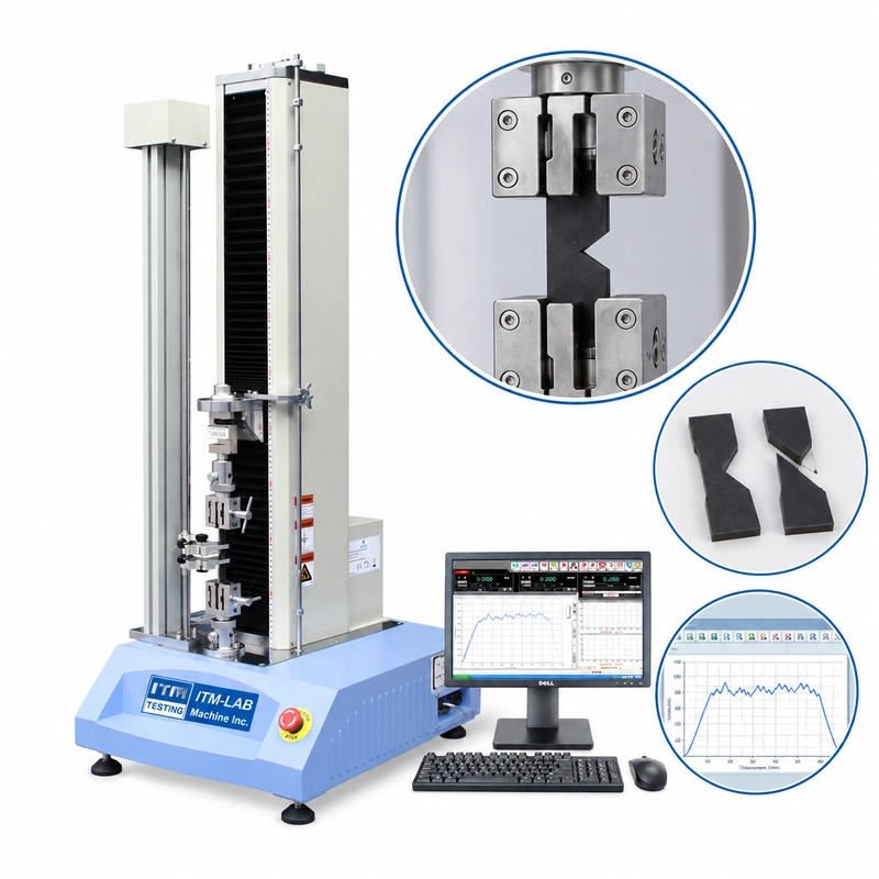
Two test pieces come from the same rubber sheet.
One gives a tear strength of 18 N/mm. The other gives 27 N/mm.
It is tempting to conclude that the second piece represents tougher rubber.
That conclusion may be wrong.
Change the specimen geometry, nick, cutting direction, stretching speed, or test temperature and the result can change even though the rubber compound has not.
That is one of the most important things to understand about ISO 34-1 rubber tear strength testing.
The current edition, ISO 34-1:2022, covers three main methods for vulcanized and thermoplastic rubber: Method A with a trouser test piece, Method B with an angle test piece with or without a nick, and Method C with a nicked crescent test piece. ISO notes that the measured tear strength depends on test-piece shape, stretching speed, test temperature, and potentially the grain direction of the rubber.
For a laboratory, knowing which die to use is only the beginning.
The specimen, nick, thickness, direction, grips, force measurement, and result processing all become part of the measurement.
What Does ISO 34-1 Actually Measure?
Tear strength describes the resistance of rubber to the initiation or propagation of a tear under defined test conditions.
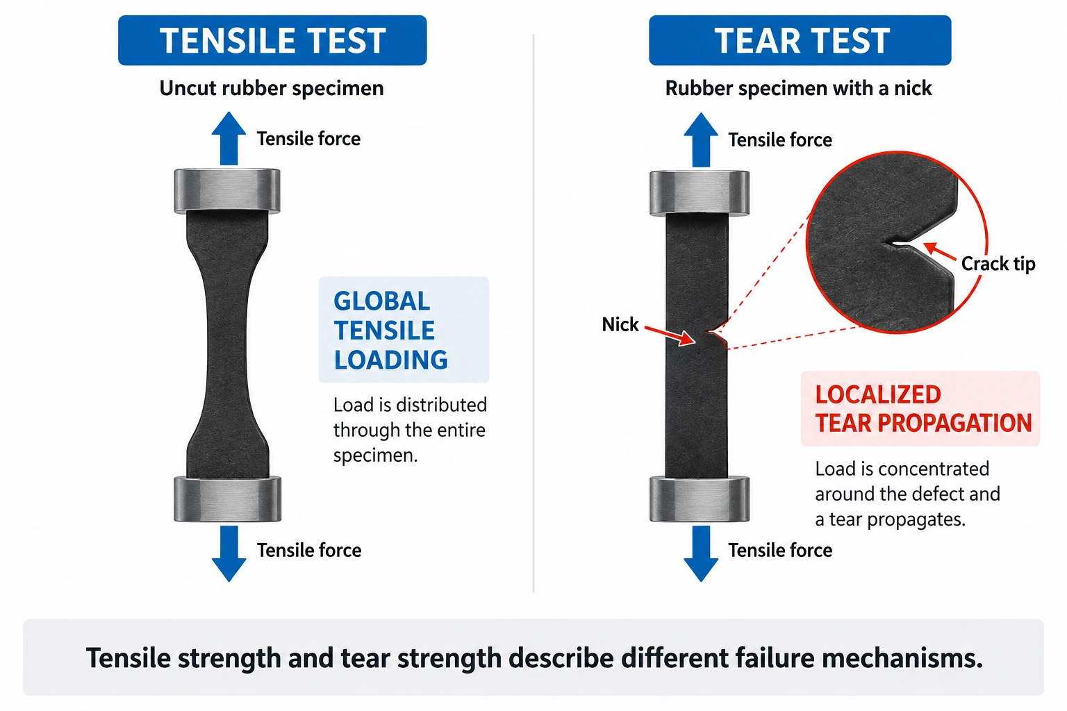
It is not another name for tensile strength.
Take an uncut rubber strip and pull it from both ends. The load is distributed through the specimen, and a tensile test characterizes the material's response to that loading condition.
Introduce a sharp angle, cut, or nick and the mechanics change.
Stress becomes concentrated around the critical region. The question is no longer simply how the material behaves under overall tensile loading, but how it responds when a tear begins or an existing defect continues to grow.
That distinction matters in real components.
A seal, boot, diaphragm, gasket, membrane, or molded elastomer can tolerate normal deformation yet become vulnerable once a small cut or edge defect exists.
ISO 34-1 creates controlled specimen geometries for investigating this behavior.
Four Test Conditions Inside ISO 34-1
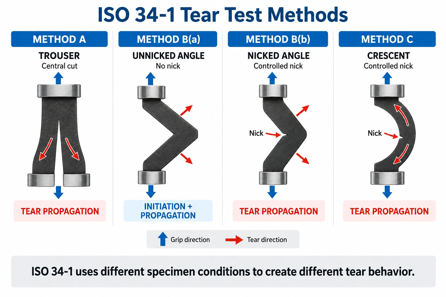
ISO 34-1 contains three main methods, but from a practical laboratory perspective there are four test configurations worth distinguishing.
The reason is Method B.
It can be performed with an unnicked angle specimen or a nicked angle specimen. Those two procedures do not create the same initial tear condition.
Method A — Trouser Test Piece
A central cut divides one end of the specimen into two legs.
Each leg is placed in a separate grip. As the grips move apart, the existing tear progresses through the specimen.
Conceptually:
Pre-cut → Grip both legs → Pull apart → Tear propagates
This is fundamentally a tear-propagation configuration. The test begins with an existing cut rather than requiring a tear to initiate from an intact edge.
Method B(a) — Unnicked Angle Test Piece
Method B(a) uses an angle specimen without a prepared nick.
As load increases, stress concentrates around the apex until a tear begins and then propagates.
The measured response therefore involves both:
Tear initiation + Tear propagation
The test does not separately resolve those two contributions.
Method B(b) — Nicked Angle Test Piece
Introduce a controlled nick and the starting condition changes.
The specimen now contains an existing defect before loading begins.
Method B(b) therefore evaluates the force associated with propagating that nick rather than first creating a tear in an intact specimen.
The distinction is simple but important:
B(a): the tear must start.
B(b): the tear has already been started.
Method C — Crescent Test Piece
Method C uses a crescent-shaped specimen with a controlled nick.
Like Method B(b), it examines propagation from an existing defect. The geometry around the tear, however, is different from the angle specimen.
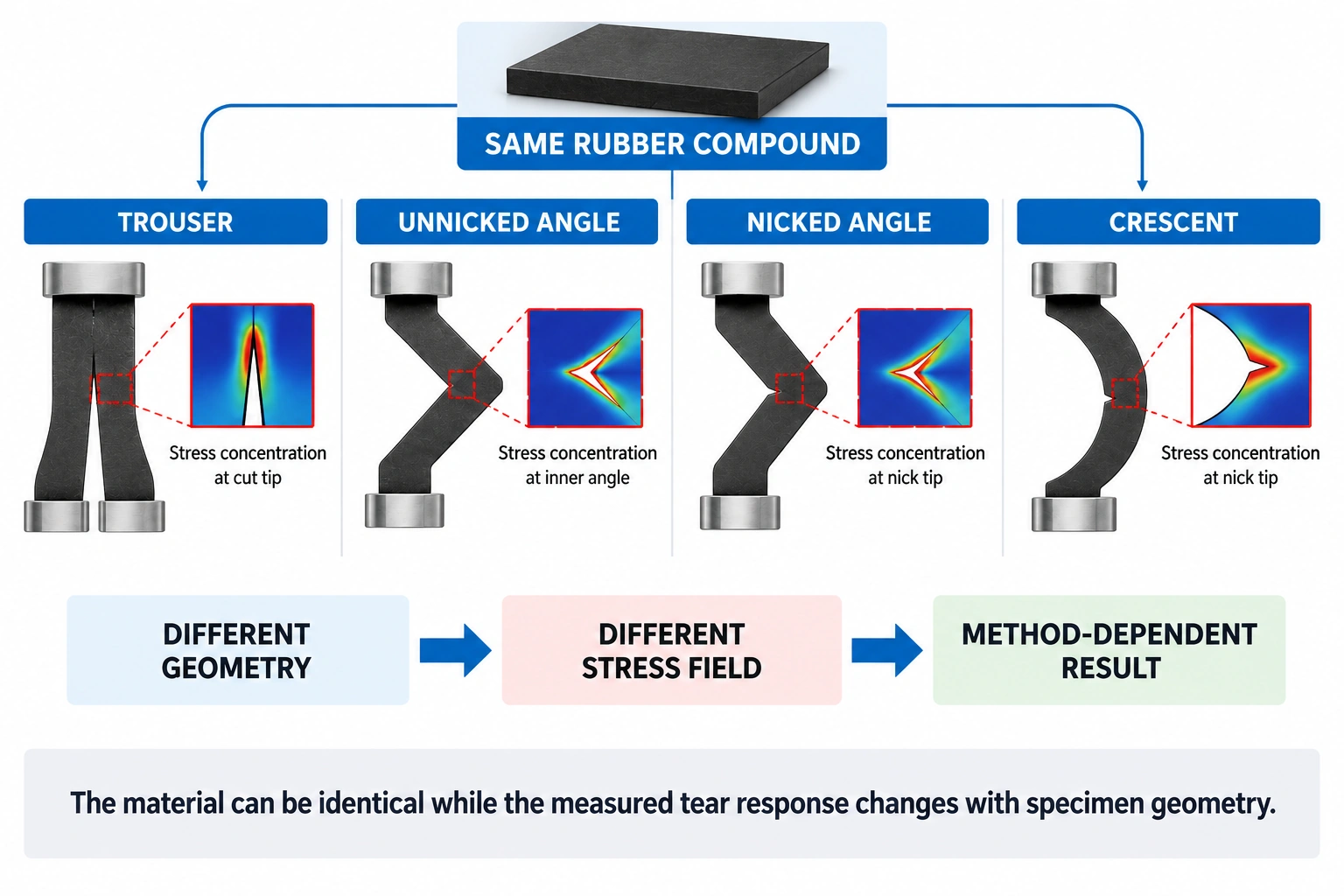
That difference in geometry is one reason the results from different ISO 34-1 methods should not be treated as interchangeable material constants.
Which ISO 34-1 Method Should You Use?
If a customer drawing, qualification document, product specification, or internal test procedure already identifies the method, use that method.
Do not substitute Method A for Method C simply because the trouser specimen is easier to prepare.
The same applies to supplier comparison.
If Supplier A was qualified using a nicked angle specimen, Supplier B should not be evaluated with a crescent specimen and then compared as though both numbers represented the same measurement.
When establishing a new internal method, consider the engineering question.
Do you need to evaluate behavior where the tear must first initiate?
Or are you interested in the propagation of an existing cut or nick?
Available specimen size can also influence which standard applies. ISO 34-1 covers trouser, angle, and crescent test pieces; small Delft test pieces are addressed separately by ISO 34-2.
There is no universal "best" ISO 34-1 method. The applicable specification and test objective should determine the procedure.
Same Rubber, Different Specimen: Why the Numbers Change
Suppose four test pieces are cut from the same EPDM sheet.
Same batch.
Same thickness.
Same conditioning.
One trouser, one unnicked angle, one nicked angle, and one crescent.
Should they all give the same N/mm?
No.
Specimen geometry changes how load is transferred toward the critical region, the local stress field around the tear, and how the rubber deforms as the crack develops.
ISO specifically notes that the measured tear-strength value depends on test-piece shape.
This is why a report that says only:
Tear Strength: 24 N/mm
is incomplete for meaningful engineering comparison.
A result such as:
24 N/mm — ISO 34-1 Method A
provides much more context.
And if another report says:
24 N/mm — ISO 34-1 Method C
the matching number does not make the two measurements mechanically equivalent.
A 1 mm Nick Is Not a Small Detail
If repeatability suddenly becomes poor, inspect the specimen preparation before blaming the load cell.
For Method B(b) and Method C, the ISO 34-1:2022 public preview specifies a nick depth of 1.0 ± 0.2 mm. Method A instead uses a central cut of 40 ± 5 mm, with approximately the final 1 mm made using a razor blade or sharp knife.
Those are small dimensions with an important job.
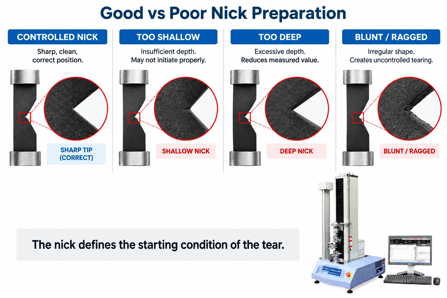
The nick defines the defect from which the tear develops.
A shallow nick leaves a different amount of material ahead of the crack. An excessively deep nick changes the remaining geometry. A blunt or ragged cut creates a different local stress condition from a clean, controlled nick.
The testing machine cannot correct any of those differences after the specimen enters the grips.
Timing also matters. The public preview states that nicked or cut specimens should preferably be tested immediately and otherwise limits the interval between cutting or nicking and testing under the stated conditions.
When repeatability deteriorates, the die, nick cutter, preparation technique, and preparation-to-test interval are all worth checking.
Thickness: How a 0.2 mm Input Error Changes the Result
Thickness is not merely a specimen-description field.
It enters directly into tear-strength calculation.
Conceptually:
Tear Strength = Relevant Tearing Force / Specimen Thickness
Consider a simple example.
Measured tearing force:
48 N
Actual specimen thickness:
2.0 mm
Calculated result:
48 / 2.0 = 24.0 N/mm
Now suppose the operator enters:
1.8 mm
The software reports:
48 / 1.8 = 26.7 N/mm
Nothing about the rubber changed.
The load cell measured the same 48 N.
Yet a 0.2 mm thickness error moved the reported value from 24.0 to 26.7 N/mm—a difference of roughly 11%.
That is why specimen measurement belongs to the test process.
The exact force evaluation and calculation procedure must still follow the selected ISO 34-1 method; not every method should be reduced to a generic maximum-force calculation.
Cutting Direction Can Look Like Test Variation
Two laboratories receive material from the same rubber sheet.
Lab A cuts its specimens in one direction.
Lab B rotates the specimen layout by 90°.
Their results disagree.
The immediate question is often:
Which machine is wrong?
Possibly neither.
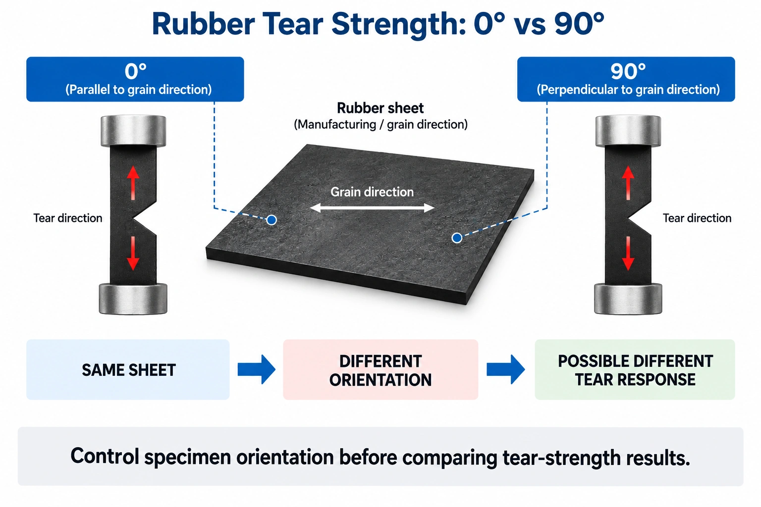
Rubber can exhibit directional behavior related to processing history, material flow, calendering, reinforcement distribution, or other structural effects.
ISO 34-1 specifically recognizes grain effects. Its public preview calls for at least five test pieces per sample and, where possible, specimens from two directions at 90° to one another so anisotropy can be evaluated.
For comparative testing, specimen orientation therefore needs to be controlled and recorded.
Otherwise a genuine material-direction effect can look like poor machine repeatability.
Speed and Temperature Are Part of the Test
A tear-strength number should not be separated from the conditions under which it was produced.
Rubber is rate- and temperature-sensitive.
Change the stretching speed and the force response can change. Change the test temperature and the material response can change again.
ISO identifies both stretching speed and test temperature among the factors affecting the measured tear-strength value.
For routine QC, this has a simple consequence.
If yesterday's specimens were tested using the specified speed and today's were run faster to increase throughput, the two datasets should not automatically be treated as equivalent just because they came from the same machine.
The machine needs to reproduce the test method—not merely pull the specimen apart.
How an ISO 34-1 Rubber Tear Test Is Performed
A useful workflow begins before the UTM starts moving.
First, confirm the method:
A, B(a), B(b), or C.
Then confirm material direction and prepare the correct specimen. Produce the cut or nick where required and measure specimen thickness using the applicable procedure.
Condition the test pieces according to the standard and any customer-specific requirements.
Next, install grips suitable for the specimen. Position the rubber so that the intended loading and tear direction are maintained, and make sure the test piece can be held without slipping or suffering unintended jaw damage.
Set the required test speed and run the test while recording the force response.
When the machine stops, look at the specimen before looking only at the final number.
Did the tear follow the expected path?
Did either grip slip?
Did the rubber fail at the jaw?
Was crack propagation smooth or irregular?
The curve and the physical specimen should tell a consistent story.
Finally, process the force data and calculate tear strength according to the selected method.
Do not build one generic software template and use it blindly for every ISO 34-1 procedure.
How Is Rubber Tear Strength Calculated?
At a conceptual level:
Tear Strength = Relevant Tearing Force / Specimen Thickness
The result is commonly expressed in:
N/mm
For example:
Relevant tearing force:
36 N
Specimen thickness:
2.0 mm
Illustrative result:
18 N/mm
This is a calculation example, not an ISO 34-1 acceptance criterion.
The word relevant matters.
Method A, B(a), B(b), and C do not all create the same force-displacement behavior. The result-processing procedure must therefore match the selected method.
A software template configured as:
Maximum Force / Thickness
should not automatically be assumed correct for every rubber tear procedure.
The method defines the result—not the convenience of the software.
What Does a Rubber Tear Curve Tell You?
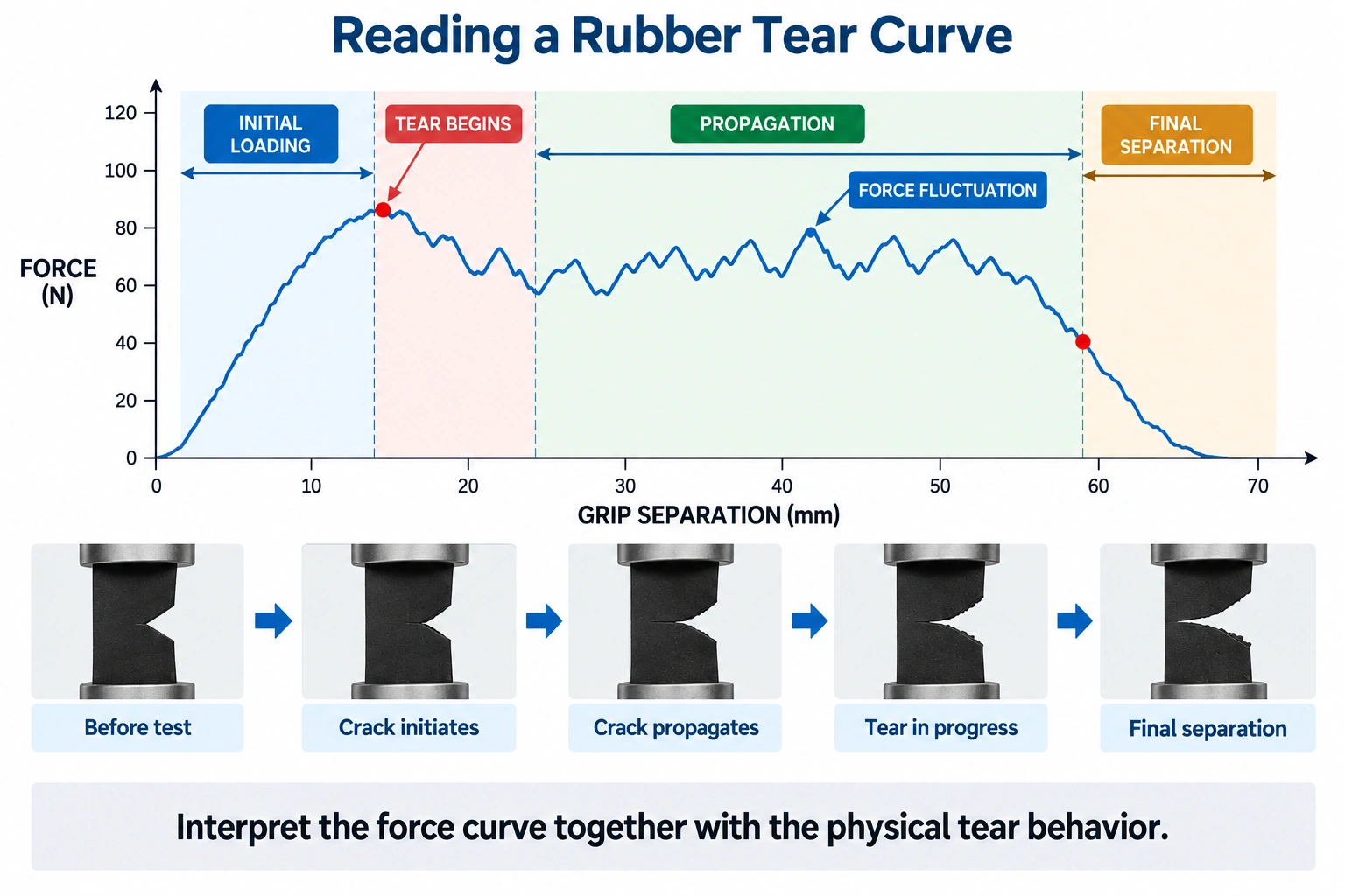
A rubber tear curve does not always look like the smooth textbook curve people expect from a tensile test.
Force may rise as loading develops and then fluctuate as the crack progresses.
Some compounds tear relatively steadily.
Others advance in a sequence closer to:
Load builds → Tear advances → Force drops → Load builds again
That does not automatically mean the UTM is unstable.
It may be the material.
The useful question is whether the force behavior corresponds with what physically happened to the specimen.
When a Strange Result Is a Test Problem, Not a Material Problem
Suppose five specimens from one batch produce:
21.4 N/mm
22.1 N/mm
21.8 N/mm
31.7 N/mm
22.3 N/mm
One result immediately stands out.
Does specimen four contain dramatically stronger rubber?
Maybe—but that would not be the first conclusion to make.
Go back to the specimen and test record.
Was its thickness entered correctly?
Was the nick prepared in the same way?
Was it cut in the same direction?
Did the specimen slip?
Did the tear follow the intended path?
Was there visible damage before testing?
Was the same speed and method used?
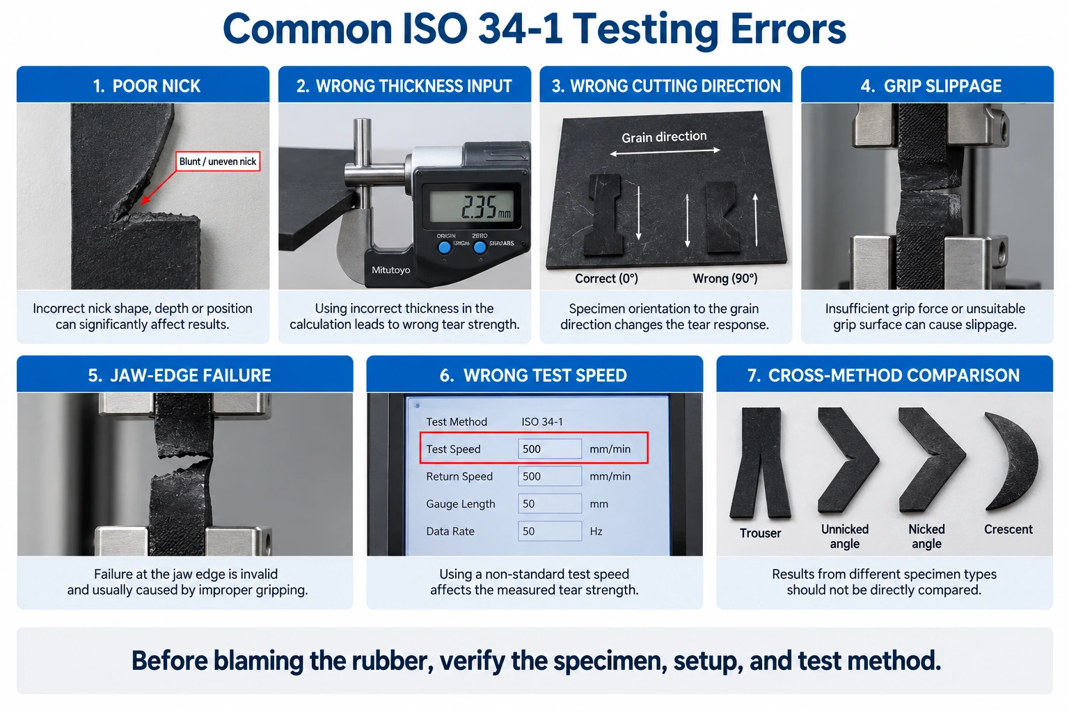
Most suspicious tear data can be investigated through three areas:
Specimen preparation: nick quality, thickness, specimen damage, and cutting direction.
Mechanical setup: grip slip, jaw damage, alignment, and force range.
Method control: specimen type, test speed, conditioning, and result-processing procedure.
Grip Selection: Where Did the Specimen Fail?
For rubber tear testing, the machine frame is only half the system.
The grips have to hold a compliant, extensible material while allowing the intended tear to develop.
A useful diagnostic is simply to look at where failure occurred.
Tear develops from the intended region
The test is behaving in the way the specimen geometry was designed to create.
Specimen slides in the grip
The gripping condition needs attention.
Grip surface, jaw design, clamping force, specimen geometry, and material hardness can all matter.
Specimen fails at the jaw edge
Do not automatically treat it as a normal tear result.
The grip may be introducing local damage or an unintended stress concentration.
Tear runs away from the intended path
Check alignment, nick preparation, specimen condition, and material direction.
This is why grip selection should be considered together with the specimen rather than added after the UTM has already been selected.
How Much Load-Cell Capacity Do You Actually Need?
Consider a test expected to produce tearing forces between:
40 and 100 N
A 5 kN machine frame has more than enough overall capacity.
That does not mean the largest available load cell is automatically the best choice.
If the useful measurement occurs below 100 N, performance in that working region matters more than having several kilonewtons of unused measurement range.
A better selection sequence is:
Expected Tear Force → Measurement Range → Load Cell → Grip → Required Travel → Machine Frame
Machine capacity and test configuration are related, but they are not the same decision.
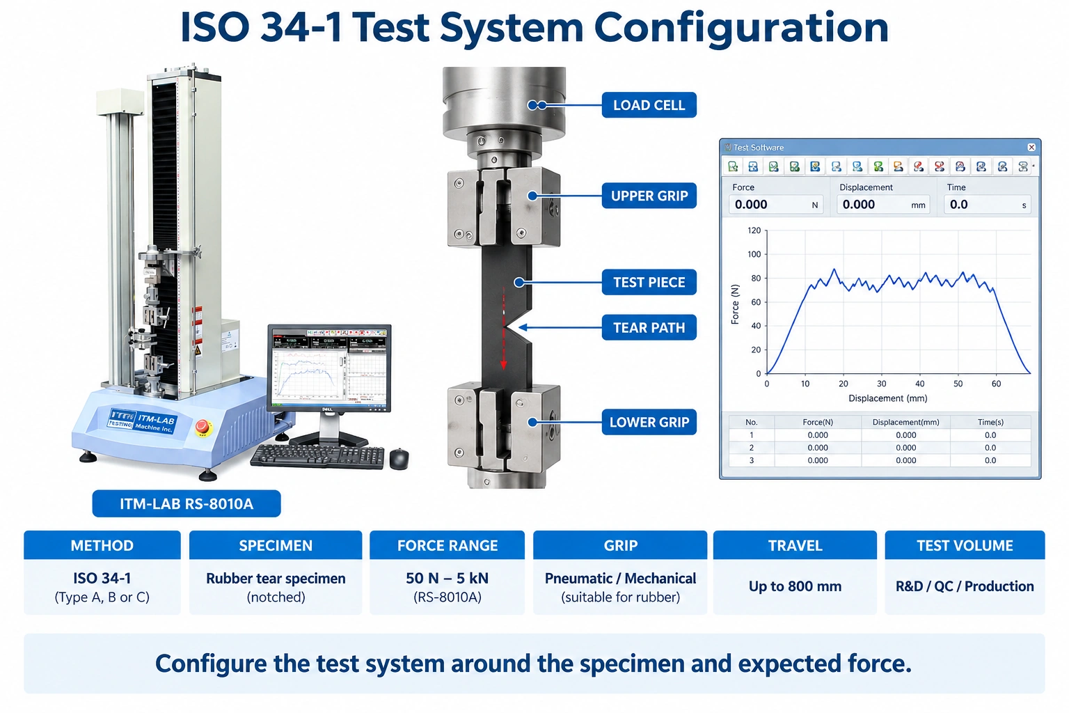
Configuring the RS-8010A for ISO 34-1
The ITM-LAB RS-8010A Universal Testing Machine is available in configurations from 50 N to 5 kN, allowing the test system to be matched to lower-force rubber and elastomer applications.
For an ISO 34-1 inquiry, we normally need to establish five things.
Method
A, B(a), B(b), or C determines the specimen and tear condition.
Expected Force
This helps define the appropriate force-measurement range.
Grip
The specimen needs to remain secure without introducing unintended failure around the jaws.
Travel
The machine must provide enough usable movement for the complete test.
Test Volume
A development laboratory testing a few specimens and a QC laboratory testing 80 or 100 specimens per day may need different grip and workflow considerations.
Software should also capture the force-displacement response and apply the result-processing logic required for the selected method.
Worked Example: Configuring an EPDM Trouser Tear Test
Consider this customer requirement:
Material: EPDM sheet
Standard: ISO 34-1
Method: A
Specimen: Trouser
Thickness: 2.0 mm
Expected Tear Force: 40–100 N
Test Volume: 80 specimens/day
Output: Tear strength + force-displacement curve
The expected force immediately tells us this is a relatively low-force application.
The measurement system should therefore be selected around the 40–100 N working region, rather than simply using the maximum force range available on the frame.
The trouser specimen adds another requirement: both legs must remain securely held while the tear progresses.
Next, verify usable travel. Force capacity alone does not tell us whether the complete tear can be accommodated.
At 80 specimens per day, grip operation also becomes important. A fixture that is mechanically adequate but unnecessarily slow to load will affect laboratory throughput.
Finally, reporting requires specimen-thickness input, the appropriate force-processing method, and curve storage.
For this application, an RS-8010A configured with an appropriately ranged load cell and suitable rubber tear grips would be a logical starting point.
Change the specimen, force range, or method and the configuration should be reviewed again.
ISO 34-1 vs ASTM D624
ISO 34-1 is not the only standard used for rubber tear testing.
ASTM D624 also addresses tear strength of conventional vulcanized rubber and thermoplastic elastomers. ASTM notes that factors such as anisotropy, stress distribution, strain rate, and specimen size can significantly influence tear behavior.
The two standards should not be casually substituted.
An ASTM D624 result does not become an ISO 34-1 result simply because both may be expressed as force per unit thickness.
The specimen geometry and test procedure define the measurement.
If the customer specification requires ASTM D624, follow ASTM D624.
If it requires ISO 34-1, follow ISO 34-1.
The same universal testing machine may be configurable for both, but specimen preparation, fixtures, software method, and procedure still need to match the applicable standard.
What We Need to Configure Your ISO 34-1 Test System
A request that says:
"Please quote a machine for ISO 34-1."
still leaves several important configuration questions unanswered.
| Information | What to Send |
|---|---|
| Rubber material | EPDM / NBR / silicone / other |
| ISO 34-1 method | A / B(a) / B(b) / C |
| Specimen | Trouser / angle / crescent |
| Specimen dimensions | Dimensions or drawing |
| Thickness | mm |
| Expected tear force | N, if known |
| Cutting direction | 0° / 90° / both |
| Required travel | If known |
| Test volume | Specimens/day |
| Customer specification | Standard / internal method |
| Sample information | Photo / drawing / existing report |
Don't Know the Expected Force?
That is common when selecting a new testing system.
Send the rubber material, method, specimen dimensions, thickness, and a specimen drawing or photo first.
Those details provide a practical starting point for defining the load cell, grips, and machine configuration.
FAQ
What is the current version of ISO 34-1?
The current published edition is ISO 34-1:2022, Edition 5, published in June 2022. It covers vulcanized and thermoplastic rubber using trouser, angle, and crescent test pieces.
What is the difference between ISO 34-1 Method A, B, and C?
Method A uses a trouser specimen. Method B uses an angle specimen and can be performed without a nick or with a nick. Method C uses a nicked crescent specimen.
Because these geometries create different tear conditions, their results should not be assumed to be interchangeable.
What is the difference between Method B(a) and Method B(b)?
Method B(a) uses an unnicked angle specimen, so the test involves tear initiation and propagation.
Method B(b) uses a nicked angle specimen, beginning with an existing controlled defect.
Is tear strength the same as tensile strength?
No.
Tensile testing evaluates material behavior under tensile loading. Tear testing creates a localized stress concentration and evaluates the initiation and/or propagation of a tear.
They describe different aspects of rubber performance.
Why is specimen thickness important?
Thickness is used in the tear-strength calculation.
An incorrect thickness measurement or software input can therefore change the reported N/mm result even when the measured force is correct.
Why does nick preparation matter?
For nicked methods, the nick establishes the crack from which the tear propagates. Its depth, sharpness, and position influence the initial crack condition.
How many specimens are required?
The ISO 34-1:2022 public preview specifies at least five test pieces per sample and, where possible, specimens from two directions 90° apart when grain effects are being assessed.
What load cell should I use for ISO 34-1?
There is no single correct capacity.
Start with the expected tearing force and select the force-measurement range around the actual working load. Then verify the grips, required travel, and machine-frame capacity.
Can the RS-8010A perform ISO 34-1 rubber tear testing?
The RS-8010A, available from 50 N to 5 kN, can be configured for lower-force rubber tear testing when the load cell, grips, travel, speed, and software method are matched to the actual application.
A Reliable Tear Result Starts With the Test Method
A tear-strength value such as 24 N/mm looks simple.
The test behind it is not.
Specimen geometry determines how the tear is loaded. Nick preparation establishes the crack. Thickness enters the calculation. Material direction can change the response. Grips determine whether the specimen remains under the intended loading condition.
So start with the method:
A, B(a), B(b), or C.
Then define the specimen, thickness, direction, expected force, grips, travel, and test volume.
For lower-force rubber tear applications, the ITM-LAB RS-8010A, 50 N–5 kN, can then be configured around those actual test requirements.
